A Case Study – The Design of the Millennium Wheel (London Eye) & Singapore Flyer
Originally conceived by architects David Marks and Julia Barfield Associates as a response to a public call for ideas to mark the turning off the Millennium in London, the Millennium Wheel (or London Eye), was always going to be a controversial project.
Its critics branded it an inappropriately placed fair ground attraction. Given its prime position in the heart of conservative London, immediately across the Thames from Westminster, Big Ben and the Houses of Parliament, it was not hard to understand their point of view.
The Millennium Wheel was granted a cautious temporary planning approval for a period of five years upon completion, after which time it was to be dismantled and re-erected somewhere else. The structure was designed in fact to resist the higher winds loads of Blackpool further north in England where it was arguably going to end up. Marks was adamant however that similar to the Eiffel Tower in Paris, the quality of the design and the ride experience would see it adopted and loved by the London public and tourists alike; planning permit he maintained would be extended in perpetuity.
He was proven right. The permanent license was granted just two and a half years later in July 2002.
The quality of design infused through the project played no small part in its success and ultimate permanent position on the London skyline.
Design of Wheels
The design of the wheel is a good example of the coming together of architecture and engineering in order to serve common goals, not just one discipline or the other.
The rim and spokes of the wheel are one of the main elements that differentiate wheels from other types of structure, and represent one of the principle design challenges .
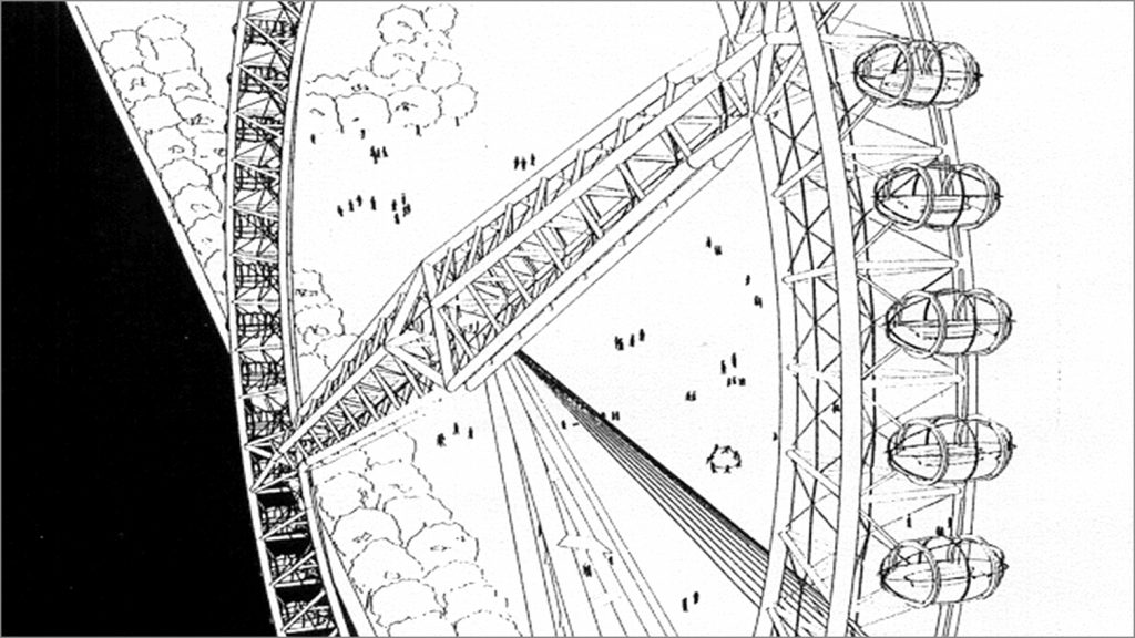
The initial conceptual idea from Marks & Barfield was an architecturally mind blowing 150m diameter wheel with an impressive single spoke cantilevering from the central support.
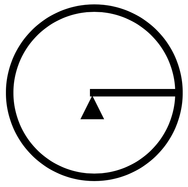
Equating to the structural equivalent of a 225m cantilever by the time the span was taken back to the opposite side of the supported rim, the scheme presented significant structural challenges. As enticing as the idea was, a few quick calculations revealed the immense steel tonmnmage and cost that wouldnbe required to make it work. The single spoke was doubled to two spokes after engineering input by Arup.
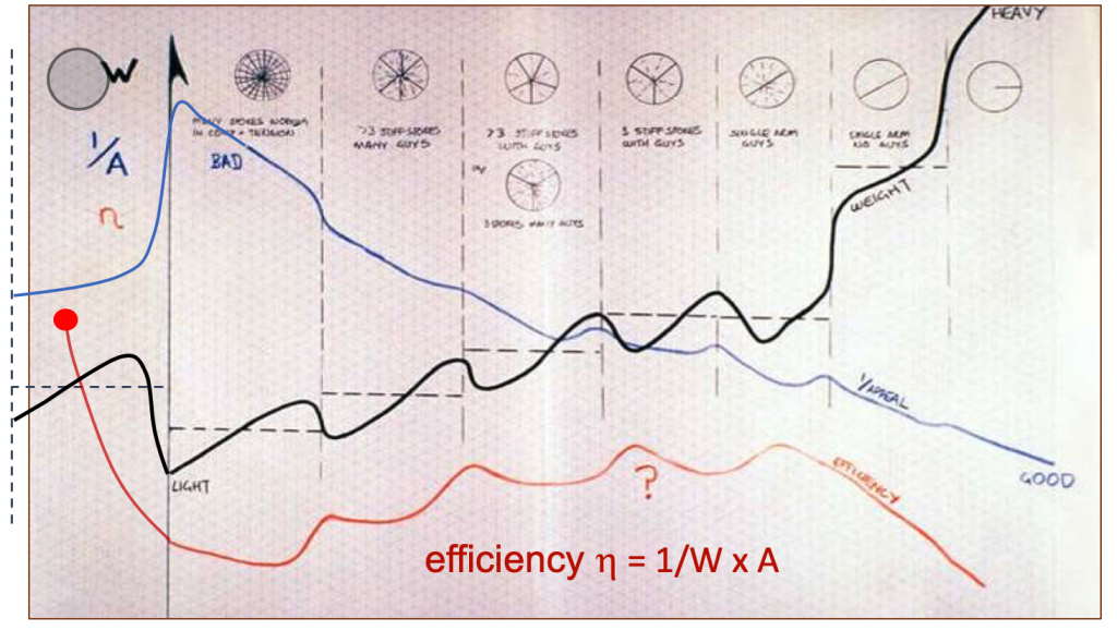
Once on this path of design exploration, the obvious question was raised as to how many spokes were appropriate, why stop at adding one? The focus of the early stages of the conceptual design then became a study of the trade offs between aesthetic appeal and structural efficiency & cost for different wheel arrangements.
Recognising the internal design tensions that these studies represented, the team formulated an overall project design efficiency equation that considered all of the inputs into the project, against the outputs. Inputs included tonnes of steel, cost of labour, impact to the environment etc.; while the outputs included aesthetic appeal, cost to construct, and generation of tourism, and so on.
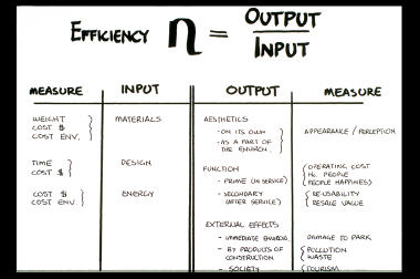
The efficiency of particular arrangements was assessed as the product of aesthetic appeal and functionality, divided by the structural weight, a holistic project value per kg of steel if you like. The resulting exploration considered many forms of varying numbers and types of spokes; in the end a many spoked tension wheel came to the forefront as a clear winner. The weight savings offered by the structural efficiency of the many spoked bicycle wheel form, along with the aesthetic appeal of the light cable spokes trumped all the solutions.
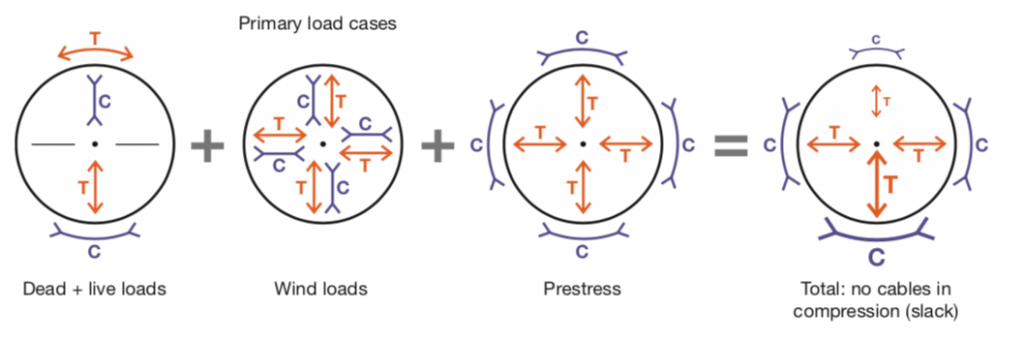
The bicycle wheel arrangement derives its efficiency through the many tension spokes effectively providing continuous support to the rim which acts in hoop compression to resolve the tensions in the spokes.
The resulting form adopted and built was a resounding architectural and engineering success.
Almost There
While the overall form of the wheel was truly a joint effort between architect and engineer, the detailing was not. Marks and Barfield demanded a heavy architectural merit weighting on this front. Design decisions in this respect included the triangular form of the rim and requirement for the cables to meet at the triangle apex of the rim truss, rather than at the sides.
Wheel Design 2.0 – Singapore
Taking the London Eye as inspiration, the next generation of observation wheel design was developed through the design of the Singapore Flyer.
In contrast to the lofty public value ideals of the London Eye in creating an icon to mark the turn of the century, the Singapore Flyer was a purely development driven prospect from the start. It’s primary interest was in maximising financial return on (private), investment.
With the intention of minimising weight, and therefore cost, the engineers (again Arup), were allowed unfettered control of the design. Learning from the London Eye a number of engineering initiatives were introduced.
- The width of the support structure was maximised increasing the spoke cable inclination, and therefore efficiency to resist wind loads.
- The rim was changed from a triangel to a rectangular box.
- The spoke cables were fixed to the outside of the rim (now a box), rather than the central apex of the triangular rim of the Eye, further increasing cable angle and efficiency.
The London eye experience had taught the design engineers the exagerated importance of dead load (vertical gravity loads) on the design. The dead load governs the amount prestress or tension/tightening that is required in the spokes to avoid them going going slack (slack cables means loss of rim restraint and an effectively longer spanning rim structure).
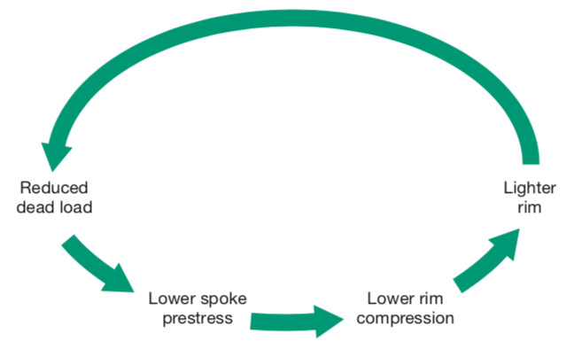
As tensions in the spokes are resolved circumferentially around the wheel into a compression in the rim (similar to a bicycle wheel), a virtuous design circle exists: Decreases in spoke tensions leads to decreases in rim compression, decreased rim compression requires less steel in the rim to resist it, and less steel in the rim means decreased dead loads – we end up back at the start of thedesign circle able to reduce spoke tensions again… A virtuous design circle that amplifies the benefits of reduced initial weight is set up.
The reverse is also true in that increased dead loads lead to a vicious design circle where tensions and rim compressions and weights are all subsequently increased.

Following the efficiencies gained by this virtuous design circle, the rectangular form of the rim was able to be reduced to a simple two dimensional ‘ladder truss’ form. At the end of the design process, the Singapore Flyer was 15% larger than the London Eye however weighed 15% less in total steel tonnage. Significant savings when it comes to a commercial performance.
Both projects are good examples of the interplay between architecture and engineering in design. The different approaches demonstrate how the balance can be altered to serve specific end project goals and outcomes peculiar to the developoment environment.
Aesthetics and architectural merit in the case of the London Eye, and costs and return on investment in terms of ther Singapore Flyer.
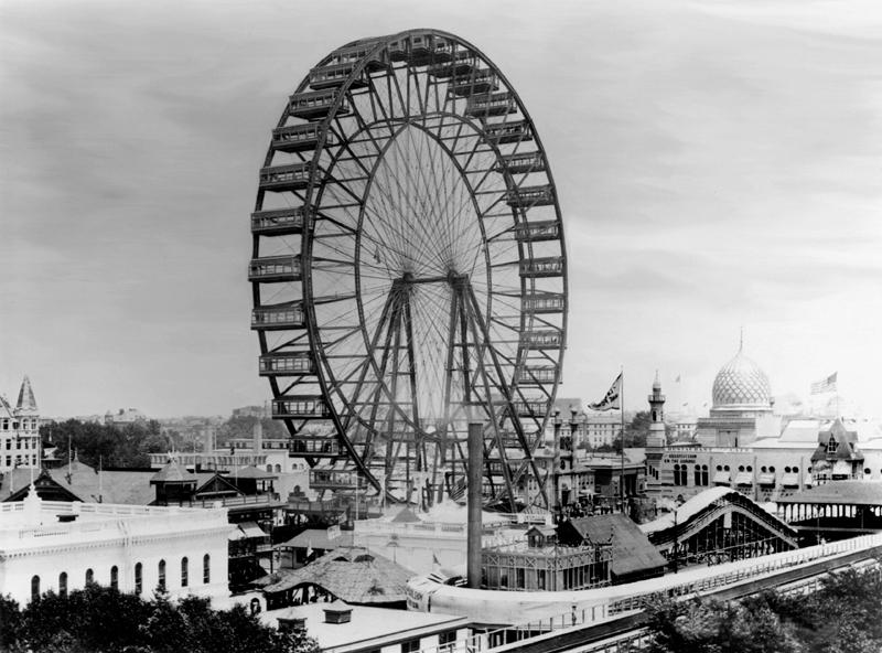
It is interesting to consider that neither the design of the London Eye or the Singapore Flyer vary considerably from the original ‘Ferris wheel’ built for the 1863 Chicago World Expo. All three wheels have the same basic form of tension spokes resolved by compression rims. The single biggest advancement has been in the provision of smooth motor driven capsules as opposed to the swinging gravity hung carriages of the original Ferris wheel. That and the advances in materials and structural engineering. The original Ferris wheel stood at 264′ or 80.4m in height, approximately half the size of today’s ‘giant observation wheels’.
Structurally the most efficient solution for a giant observation wheel is the form commonly seen in fair grounds and amusement parks. It involves many small compression members ‘laced’ together to structural restrain and support each other. Lightweight, but not altogether inspiring…
The many tension spoked bicycle wheel solution first adopted in Chicago, and re-proven in London and Singapore have now become the preferred form of Giant Observation Wheel (GOW’s), design around the world. Their forms achieve a commensurate balance between architectural aesthetics & public appeal, and structural efficiency & cost, appropriate to projects that change city skylines and attract international tourists.
This article is an adaptation of the paper ‘Allsop, A., Dallard, P., & McNiven, B. (2009). The Singapore Flyer and Design of Giant Observation Wheels. Structural Engineering International, 19(1), 5.’ along with experience drawn from the author. The original paper can be found below:
Image credits
Image 1, 3, 4: design & presentation sketches Brendon McNiven (Arup).
Image 2: Competition rendering David Marks & Julia Barfield Associates.
Image 5: Arup
Image 6, 7: from Allsop, A., Dallard, P., & McNiven, B. (2009) (refer above).
Image 8: Original Ferris wheel: https://www.ajc.com/news/the-world-tallest-ferris-wheels/R79DhNw06UZkSd9825UmJK/